A real 4G and 5G network, per user, in a browser.
Trace5G boots an isolated mobile core, base station and UE for every run: real stacks on a real radio. It streams the decoded protocol trace into a live analyzer. Every figure on this page was measured on a run that actually happened.
Sources. Record count and duration: a saved 4G trace.
Boot time: a 5G SA run on trace5g.com, 2026‑09‑10. Layer count: the distinct
layer values in that run’s own trace. Interfaces and specification count: the
product’s source.
Overview
Most telecom “simulators” replay a script. Trace5G does not. You compose a network on a canvas (base station, UEs, core functions, an IMS), press Run, and a real stack boots: a real core, a real base station and a real UE radio talking to each other over a real air interface, in an environment allocated to that one run.
What that buys you
| Property | What it means in practice |
|---|---|
| Real signalling | RRC, NAS, NGAP/S1AP, PFCP, Diameter and SIP are produced by the stacks themselves, then decoded from the capture with the 3GPP ASN.1 definitions. Nothing is templated. |
| Real radio | PHY, MAC, RLC and PDCP are the base station’s and the UE’s own. Bandwidth, PRB count, modulation order and HARQ are whatever the scheduler actually chose. |
| Real user plane | A ping is ICMP over the UE’s bearer through the user-plane function to the internet. A download is HTTPS over that same bearer. The bytes cross the air interface. |
| Isolation | Your network does not share a core, an IP range or a spectrum plan with anyone else’s. |
| Empty means empty | A field with no measured value shows —. The platform never fills a gap with a plausible number. |
How a run works
You press Run. The progress panel names the stage the network is in and holds there until it really reaches the next one.
| Stage | What happens | Typical |
|---|---|---|
| 1 | Your topology becomes real configuration: the cell, the core, the subscriber database, the IMS | seconds |
| 2 | The core starts and its functions register with each other | ~1 min |
| 3 | The base station comes up and the UE searches for it, syncs and attaches | ~1–2 min |
| 4 | The decoded trace streams into the analyzer while the network stays up | until you stop it |
Measured on trace5g.com: 1 m 40 s from pressing Run to the first decoded record, and 9,654 records by the time that run was stopped 541 s later.
Every run is yours alone. Your network does not share a core, an IP range or a radio with anyone else, so its timing is its own.
Networks supported
Three networks, all real, all on the same radio.
| Capability | 4G LTE | 5G SA | 5G NSA (EN-DC) |
|---|---|---|---|
| Attach / Registration | OK | OK | OK |
| Default bearer / PDU session | OK | OK | OK |
| IMS registration (VoLTE / VoNR) | OK | OK | OK |
| MO / MT voice call | OK | OK | OK |
| Two-way voice media (RTP) | 68.7 / 68.8 kbit/s | OK | 68.8 kbit/s |
| SMS over IMS | OK | OK | OK |
| Ping / latency | 0 % loss, 30 ms med | 0 % loss, 39 ms med | 0 % loss, 82 ms med |
| Internet download | 2.28 MB/s @10 MHz | 0.77 MB/s @20 MHz | 0.85 MB/s @10 MHz |
| EN-DC secondary cell | — | — | OK |
| Dedicated QoS flow via AF | — | available | — |
| Inter-cell move / handover | available | available | — |
| 256QAM downlink | OK | — | OK |
Reading this table. OK means a run did it and its
verdict recorded it. available means the product offers it and it has its
own tests, and it is shown elsewhere on this page rather than here.
— means not applicable to that network.
Nodes
What you can place on the canvas, what it really is, and where it is defined.
5G core (5G SA)
| Node | Role | Reference |
|---|---|---|
| AMF | Access and Mobility Management: terminates N1 NAS and N2 NGAP | TS 23.501 · TS 24.501 · TS 38.413 |
| SMF | Session Management: PDU sessions, N4 towards the UPF | TS 23.501 · TS 29.244 |
| UPF | User Plane: GTP-U on N3, internet on N6 | TS 23.501 · TS 29.281 |
| AUSF | Authentication Server: 5G-AKA | TS 33.501 §6.1.3.2 |
| UDM | Unified Data Management: subscriber data, key derivation | TS 23.501 · TS 35.206 |
| UDR | Unified Data Repository | TS 23.501 |
| PCF | Policy Control: QoS rules, N5 from the AF | TS 23.503 · TS 29.514 |
| NRF | NF Repository: registration and discovery of every function | TS 29.510 |
| BSF | Binding Support Function | TS 23.501 |
| NSSF | Network Slice Selection | TS 23.501 |
| gNB | 5G NR base station: the real radio | TS 38.300 · TS 38.331 |
4G core (EPC)
| Node | Role | Reference |
|---|---|---|
| MME | Mobility Management Entity: S1-MME, NAS-EPS | TS 23.401 · TS 24.301 · TS 36.413 |
| HSS | Home Subscriber Server: S6a Diameter | TS 29.272 |
| PCRF | Policy and Charging Rules: Gx | TS 29.212 |
| SGW-C / SGW-U | Serving Gateway, control and user plane split | TS 23.214 · TS 29.244 |
| PGW-C / PGW-U | PDN Gateway, control and user plane split | TS 23.214 · TS 29.274 |
| eNB | LTE base station: the real radio | TS 36.300 · TS 36.331 |
| NR cell | en-gNB secondary cell group, hosted by the eNB (EN-DC) | TS 37.340 |
IMS
The CSCF chain and the IMS subscriber database: what a session between two subscribers of one IMS needs, from REGISTER through to the media.
| Node | Role | Reference |
|---|---|---|
| P-CSCF | Proxy CSCF: the UE’s first SIP hop, on Gm | TS 23.228 · TS 24.229 |
| I-CSCF | Interrogating CSCF: Cx to the HSS on registration | TS 29.228 |
| S-CSCF | Serving CSCF: IMS AKA, registration state, call routing | TS 33.203 §6.1 |
| IMS HSS | IMS subscriber database, its own Diameter realm | TS 29.228 · TS 29.229 |
| AF | Application Function: asks the PCF for a dedicated QoS flow on N5 | TS 29.514 |
Interfaces
The canvas draws 34 interfaces and the run carries them. These are the reference points, not labels on a picture: traffic on them appears in the trace under the interface’s own name.
| Interface | Between | Carries | Reference |
|---|---|---|---|
| N1 | UE ↔ AMF | NAS-5GS | TS 24.501 |
| N2 | gNB ↔ AMF | NGAP over SCTP | TS 38.413 |
| N3 | gNB ↔ UPF | GTP-U | TS 29.281 |
| N4 | SMF ↔ UPF | PFCP | TS 29.244 |
| N5 | AF ↔ PCF | Npcf policy authorization | TS 29.514 |
| N6 | UPF ↔ Internet | user IP | TS 23.501 |
| N7 · N8 · N10 · N11 · N12 · N13 · N15 · N22 · N35 · N36 | between core functions | service-based HTTP/2 (SBI) | TS 29.500 · TS 23.502 |
| S1-MME | eNB ↔ MME | S1AP over SCTP | TS 36.413 |
| S1-U | eNB ↔ SGW-U | GTP-U | TS 29.281 |
| S5-C / S5-U | SGW ↔ PGW | GTP-C / GTP-U | TS 29.274 |
| S6a | MME ↔ HSS | Diameter | TS 29.272 |
| S11 | MME ↔ SGW-C | GTP-C | TS 29.274 |
| Sxa / Sxb | SGW-C ↔ SGW-U, PGW-C ↔ PGW-U | PFCP | TS 29.244 |
| Gx | PGW-C ↔ PCRF | Diameter | TS 29.212 |
| SGi | PGW-U ↔ Internet | user IP | TS 23.401 |
| Gm | UE ↔ P-CSCF | SIP over the UE’s own bearer | TS 24.229 |
| Mw | between CSCFs | SIP | TS 24.229 |
| Cx | I/S-CSCF ↔ IMS HSS | Diameter (UAR/UAA, MAR/MAA, SAR/SAA) | TS 29.228 |
| EN-DC | eNB ↔ NR cell | secondary cell group config inside LTE RRC | TS 37.340 §4.1 |
| Uu / NR-Uu | base station ↔ UE | the air interface itself | TS 36.331 · TS 38.331 |
Protocol coverage
Not a list of what the analyzer could decode. This is a count of what two real runs actually produced. Every layer below appeared in the trace, with its own channel, direction and decode.
| Layer | a 4G run | a 5G NSA run | What is decoded | Reference |
|---|---|---|---|---|
| RRC | 20,699 | 76,215 | full ASN.1 IE tree, both E-UTRA and NR | TS 36.331 · TS 38.331 |
| PDCP | 63,842 | 26,281 | SN, integrity / ciphering state, SDU length | TS 36.323 · TS 38.323 |
| RLC | 57,806 | 61,876 | AM/UM PDUs, status PDUs, ACK_SN, retransmissions | TS 36.322 · TS 38.322 |
| MAC | 35,431 | 18,580 | subheaders, LCIDs, control elements, RAR, padding | TS 36.321 · TS 38.321 |
| PHY | 832 | 5,586 | PDCCH / PDSCH / PUSCH / PUCCH, MCS, modulation order, RV, CRC, SNR | TS 36.211 · TS 38.211 |
| NAS | 1,229 | 633 | EPS and 5GS NAS, security context, identity, session messages | TS 24.301 · TS 24.501 |
| NGAP / S1AP | 44 | 102 | procedure code, protocol IEs, NAS-PDU carried inside | TS 38.413 · TS 36.413 |
| GTP | 20,627 | 10,444 | GTP-U TEID and QFI, GTP-C session messages | TS 29.281 · TS 29.274 |
| PFCP | 4 | 127 | session establishment / modification on N4, Sxa, Sxb | TS 29.244 |
| Diameter | 12 | 49 | S6a, Gx and Cx: CER/CEA, UAR/UAA, MAR/MAA, DWR/DWA | TS 29.272 · TS 29.212 · TS 29.228 |
| SIP | — | 121 | REGISTER, INVITE, MESSAGE, BYE, responses, SDP | TS 24.229 |
| SBI | — | — | HTTP/2 service-based calls between 5G core functions | TS 29.500 |
On the two empty cells. The 4G run had no IMS in its topology, so it produced no SIP. Neither run is 5G SA, so neither produced SBI. A 5G SA run does: on trace5g.com run a 5G SA run had SBI as its fourth busiest layer with 864 records, beside SIP 153, Diameter 96 and PFCP 220.
Channels seen in one 4G run
// distinct `channel` values in a 4G trace
DRB1   SRB1   SRB2   CCCH        // radio bearers and the common control channel
DL-SCH UL-SCH PDCCH PDSCH        // transport and physical channels
PUSCH  PUCCH                      // uplink shared and control
S1-MME S1AP  NAS   GTP            // core-facing
Radio profiles
Every parameter here is written into the real cell configuration and really boots. The band is a number on this radio; see the FAQ for exactly what that does and does not mean.
4G LTE and the NSA anchor
| Band | Centre | DL EARFCN | Default | Reference |
|---|---|---|---|---|
| 1 | 2100 MHz | 0–599 | 300 | TS 36.101 Table 5.7.3-1 |
| 3 | 1800 MHz | 1200–1949 | 1575 | |
| 7 | 2600 MHz | 2750–3449 | 3100 | |
| 8 | 900 MHz | 3450–3799 | 3625 | |
| 20 | 800 MHz | 6150–6449 | 6300 | |
| 28 | 700 MHz | 9210–9659 | 9435 |
| Channel | n_PRB | Cell rate |
|---|---|---|
| 5 MHz | 25 | 7.68 MS/s |
| 10 MHz | 50 | 15.36 MS/s |
| 15 MHz | 75 | 23.04 MS/s |
| 20 MHz | 100 | 30.72 MS/s |
Channel bandwidth is physically real, and the throughput follows it. Measured on three labs of one run: 5 MHz → 1.16 MB/s, 15 MHz → 1.77 MB/s, 20 MHz → 2.26 MB/s, all at 0 % ping loss.
5G NR
| Band | Duplex | SCS | Channels | 5G SA | EN-DC |
|---|---|---|---|---|---|
| n1 | FDD | 15 / 30 kHz | 5–20 MHz | yes | yes |
| n3 | FDD | 15 / 30 kHz | 5–30 MHz | yes | yes |
| n7 | FDD | 15 / 30 kHz | 5–50 MHz | yes | yes |
| n28 | FDD | 15 / 30 kHz | 5–40 MHz | yes | yes |
The UE radio runs 15 kHz subcarrier spacing, so these four FDD bands are the supported set in 5G SA and in EN-DC. Reference: TS 38.101-1 Table 5.2-1 for the duplex mode, Table 5.3.5-1 for the channels.
Other radio parameters
| Parameter | Range | Reference |
|---|---|---|
| PCI | 0–503 (LTE) · 0–1007 (NR) | TS 36.211 §6.11 · TS 38.211 §7.4.2 |
| TAC | 0–65535 | TS 36.413 §9.2.3.7 |
| PLMN (MCC/MNC) | editable | TS 23.003 |
| TX / RX gain | editable, dB | — |
| Antennas | 1 TX · 1 RX (SISO) | fixed today |
| SIB1: q-RxLevMin, cellBarred, intraFreqReselection, si-WindowLength | editable | TS 36.331 §6.3.1 · TS 38.331 §7.1 |
| SIB2 RACH: numberOfRA-Preambles, preambleInitialReceivedTargetPower, powerRampingStep, preambleTransMax, ra-ResponseWindowSize, mac-ContentionResolutionTimer | editable | TS 36.331 §6.3.2 |
| Timers: T300, T301, T310, N310, T311, N311 | editable | TS 36.331 · TS 38.331 |
Scenario library
A scenario is a list of real commands run against the live network after it boots. You build one in the Run dialog, or fire single actions from a node’s menu while the run is up. Every action below executes on the real node of the run.
Registration / Attach
The UE finds the cell, authenticates and attaches.
TS 24.501 §5.5.1 · TS 24.301 §5.5.1PDU session / bearer
The default data bearer is established end to end.
TS 24.501 §6.4.1 · TS 23.401UE capability
The network asks, the UE declares its bands and features.
TS 36.331 §5.6.3 · TS 38.331 §5.6.1EN-DC cell addition
B1 report, then the NR secondary cell group is added.
TS 37.340 §10.2IMS registration
SIP REGISTER, AKA challenge, 200 OK, reg-event NOTIFY.
TS 24.229 §5.1.1 · TS 33.203 §6.1Voice call
MO/MT INVITE, SDP offer/answer, two-way RTP, BYE.
TS 24.229 §5.1.3 · TS 26.114SMS over IMS
SIP MESSAGE between two subscribers.
TS 24.341 §5.3.2Latency
ICMP over the UE’s own bearer to the gateway.
user planeThroughput
A timed HTTPS download across the air interface.
user planeSwitch a UE off / on
Detach and re-attach, to watch the whole bring-up again.
TS 24.501 §5.5.2Stop a core function
Kill the AMF, the UPF or the HSS and read what breaks.
failure injectionAF QoS request
The Application Function asks the PCF on N5 for a dedicated flow.
TS 29.514The full action list
| Action | What it really does | Target |
|---|---|---|
| ue.start / ue.stop | Starts or stops the UE process: a real detach and re-attach | UE |
| ue.deregister | Sends a NAS deregistration | UE |
| ue.status / ue.ps-list | Reads the UE’s own state and PDU session list | UE |
| pdu.establish / pdu.release | Adds or releases a PDU session on a named DNN | UE |
| traffic.ping | ping from the UE itself, on its own tunnel interface | UE |
| traffic.web | A timed HTTPS download over the UE’s bearer | UE |
| ims.register / ims.deregister | SIP REGISTER / de-REGISTER from the UE’s IMS client | UE |
| ims.call / ims.hangup | SIP INVITE to another subscriber, then BYE | UE → UE |
| ims.sms | SIP MESSAGE carrying your text to another subscriber | UE → UE |
| ims.status | Reads the IMS client’s registration and call state | UE |
| af.session / af.release | The AF asks the PCF for, or releases, a dedicated QoS flow | UE via AF |
| radio.move | One cell fades down and the other rises; the UE measures both and reports | UE |
| nf.stop / nf.start | Stops or starts any core function in the topology | any node |
Registration & Attach
provenTS 24.501 §5.5.1 · TS 24.301 §5.5.1 · TS 38.331 §5.3.3The UE searches the configured channel, reads the broadcast, does random access, sets up an RRC connection, and runs authentication and security before the core accepts it.
What the trace shows, in order
// 5G SA, from a run on trace5g.com
PHY   Cell Search: changing frequency to EARFCN=1575
PHY   SYNC:  Set DL EARFCN=1575, f_dl=1842.5 MHz, f_ul=1747.5 MHz
PHY   Cell Search: Found cell with PCI=1 with 50 PRB
MAC   RA:    Rx: RAPID=3, TA=0, T-CRNTI=0x46
RRC   c-rnti=0x4601: DL rrcSetup (295 B)
RRC   c-rnti=0x4601: DCCH UL rrcSetupComplete (27 B)
NGAP  PDU ran_ue=0: InitialUEMessage
NAS   Authentication Request / Response      // 5G-AKA, TS 33.501 §6.1.3.2
NAS   Security Mode Command (eea: EEA0, eia: 128-EIA2)
NGAP  PDU ran_ue=1 amf_ue=2: InitialContextSetupRequest
      └ carries NAS : Registration Accept
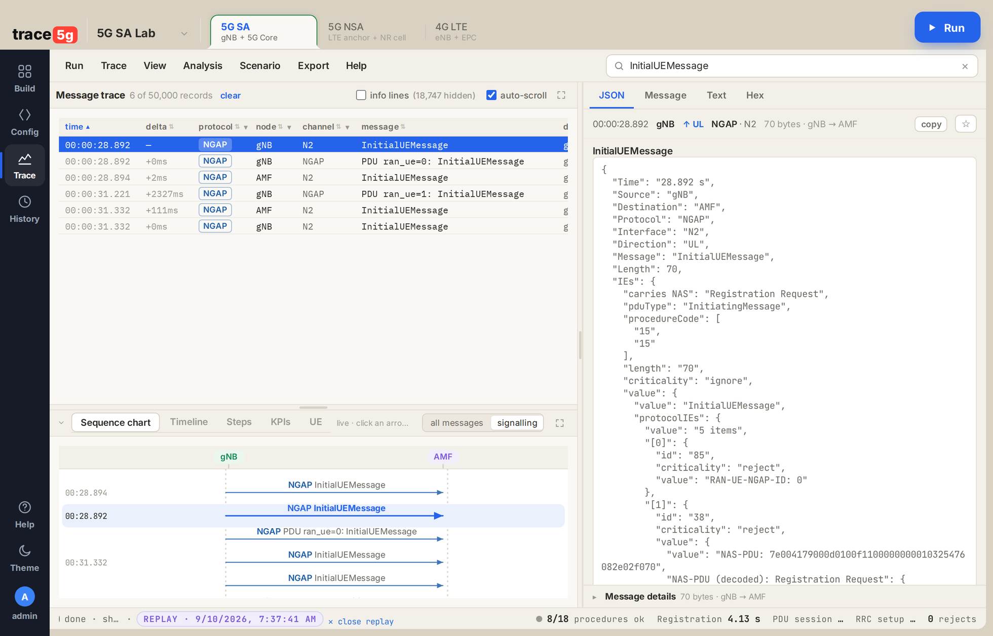
A 5G SA lab, replayed in the analyzer. 1 the NGAP InitialUEMessage the base station sends to the AMF on N2. 2 its decode: RAN-UE-NGAP-ID 0, the NAS-PDU it carries, and that PDU decoded as a Registration Request down to the 5GMM header. 3 the ladder, both UEs doing it.
Every line is a record in the trace, clickable, with its own hex and IE tree.
The frequency arithmetic is real
Band 3, EARFCN 1575 gives 1842.5 MHz down and 1747.5 MHz up, the exact 95 MHz band-3 duplex spacing of TS 36.101. Set an EARFCN outside the band and the UE finds nothing and never attaches.
PDU session & default bearer
provenTS 24.501 §6.4.1 · TS 29.244 · TS 23.401Registration alone moves no user data. The session setup is what gives the UE an IP address and a tunnel through the user plane to the internet.
// what appears across four layers for one session
NAS   PDU Session Establishment Request / Accept
NGAP  PDUSessionResourceSetupRequest → PDUSessionResourceSetupResponse
PFCP  Session Establishment Request / Response   // SMF → UPF on N4
GTP   Tunnel added. teid=0x000000…                // the user-plane tunnel exists
RRC   rrcReconfiguration (adds the data radio bearer)
GTP   UL teid=0x00ae0c: TX PDU, pdu_len=64 qfi=QFI-1
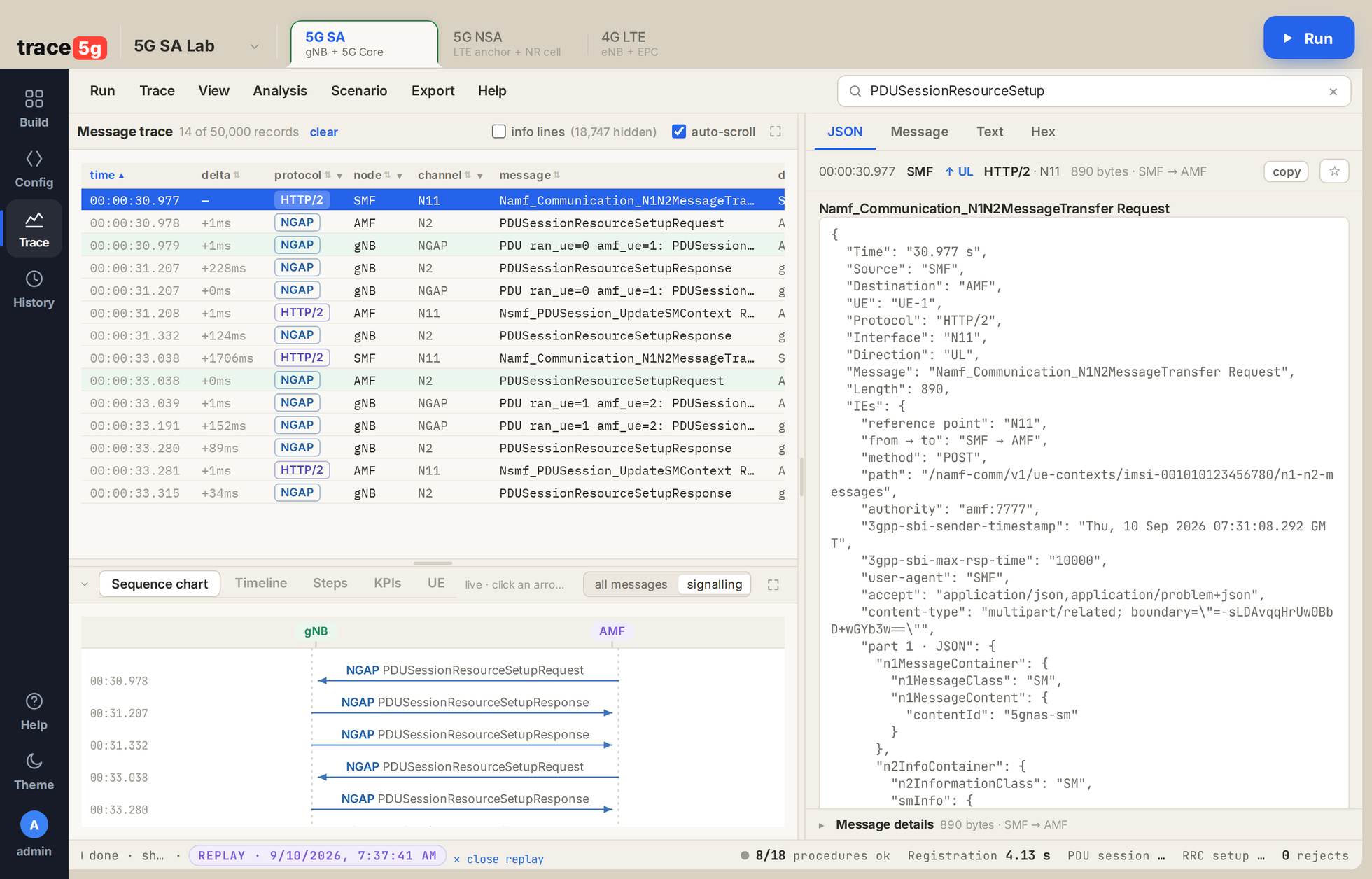
A 5G SA lab. 1 the service-based call that starts it: Namf_Communication_N1N2MessageTransfer from the SMF to the AMF on N11, over HTTP/2. 2 its multipart body, carrying the N1 SM container for the UE and the N2 PDU_RES_SETUP_REQ for the base station. 3 the NGAP setup request and response that follow on N2.
UE capability enquiry
provenTS 36.331 §5.6.3 · TS 38.331 §5.6.1 · TS 36.306The network asks what the UE can do; the UE answers with a container that the analyzer decodes down to the leaf. The container is an opaque octet string on the wire; what you read is the ASN.1 inside it.
// 5G SA, UL ueCapabilityInformation (30 B)
4c 82 06 a0 40 04 00 01 e0 00 00 00 00 10 00 00 00 02 01 00 20 04 00 0a 00 00 10 00 00 40

UL-DCCH-Message → message → c1 → ueCapabilityInformation
  rrc-TransactionIdentifier : 2
  ue-CapabilityRAT-ContainerList
    [0] rat-Type : nr
        ue-CapabilityRAT-Container : 8100100007800000000040000000080400801000280000400001
        └ UE-NR-Capability (decoded)
            accessStratumRelease : rel15
            pdcp-Parameters  → supportedROHC-Profiles (10 profiles) · maxNumberROHC-ContextSessions : cs2
            rlc-Parameters   → am-WithShortSN · um-WithShortSN · um-WithLongSN
            rf-Parameters    → supportedBandListNR : [ bandNR 3 ]
                               supportedBandCombinationList : 1 item
            featureSets      → DL per CC : kHz15, fr1: mhz10
                               UL per CC : kHz15, fr1: mhz10
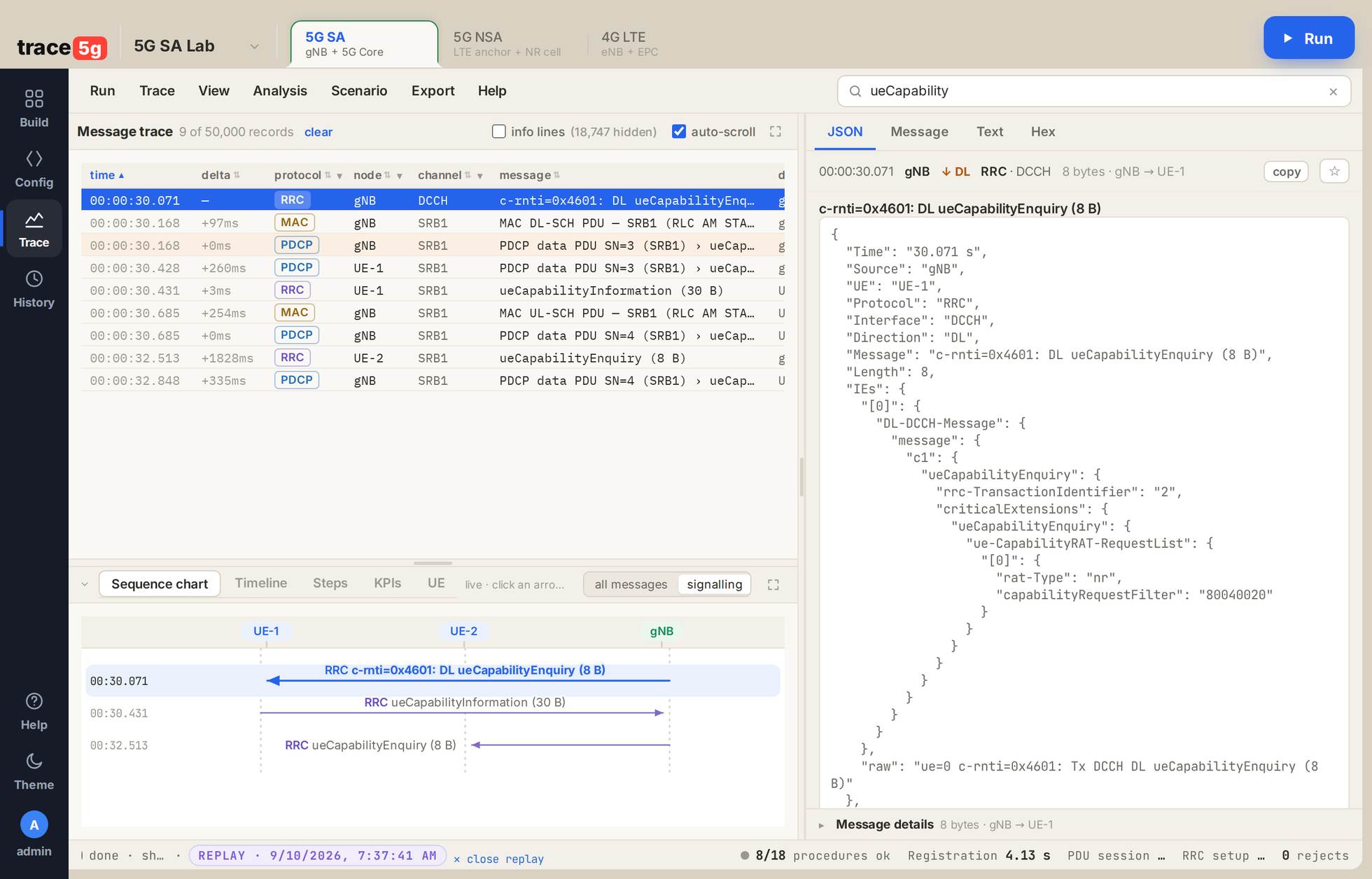
A 5G SA lab. 1 the ueCapabilityEnquiry on DCCH, 8 bytes. 2 the decoded ASN.1: ue-CapabilityRAT-RequestList with rat-Type: nr and the capabilityRequestFilter. 3 enquiry down, ueCapabilityInformation up, then the same again for the second UE.
What the UE declares
Its band, one band combination and a feature set per direction, decoded in full. The 4G capability carries more: release 14, category 4, with feature group indicators, measurement parameters and inter-RAT parameters, 102 IE nodes in one 44-byte message.EN-DC: adding the NR secondary cell
provenTS 37.340 §10.2 · TS 36.331 §5.5.4In 5G NSA the LTE cell is the anchor and the NR cell is added to the UE as a secondary cell group. There is no X2 on the wire here, because the eNB hosts the NR cell, so the whole secondary-cell configuration travels inside an LTE RRC reconfiguration.
// 5G NSA
RRC   measurementReport            // the B1 event: an NR neighbour is above threshold
RRC   rrcConnectionReconfiguration  // carries nr-SecondaryCellGroupConfig
RLC-NR  Added NR radio bearer with LCID 4 in Acknowledged Mode
RRC   drb-ToReleaseList + endc-ReleaseAndAdd-r15
      // the LTE data bearer is released and re-added on the NR leg
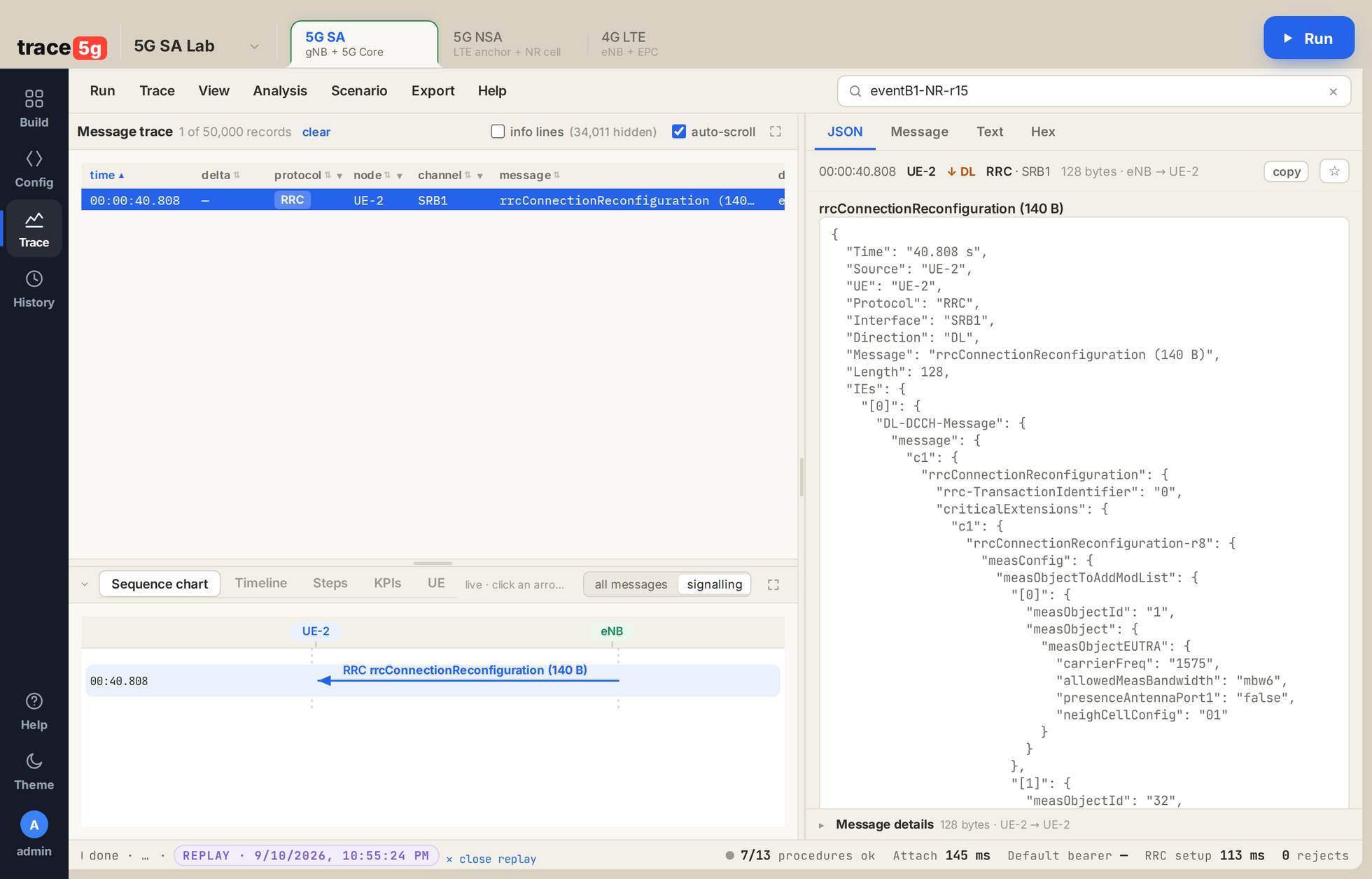
A 5G NSA lab. 1 an LTE rrcConnectionReconfiguration, 140 bytes on SRB1. 2 inside it, two measurement objects: measObjectEUTRA on carrier 1575, the band-3 anchor, and measObjectNR-r15 on carrier 367930 with its SSB timing and subcarrierSpacingSSB-r15: kHz15. That is the NR cell being configured through LTE RRC, which is why there is no X2 to see. 3 the message on the ladder.
endc, 8 measurementReport records, and NR bearer DRB2 present in the
trace’s own channel list beside the LTE DRB1.Open issue, stated
One radio link failure was seen on the second UE of an NSA run (contention resolution, 10 attempts) with no timing-advance command anywhere in its log, and the two-UE NSA IMS lab still loses about 10 % of its pings with a 704 ms tail. Both are open, neither has a cause yet, and neither is hidden here.IMS registration: VoLTE and VoNR
provenTS 24.229 §5.1.1 · TS 33.203 §6.1 · TS 29.228The IMS core boots with the lab when any UE asks for it. The UE’s SIP client registers over its own bearer, is challenged with IMS AKA, answers, and is accepted. Every SIP message crosses the air interface like any other user traffic.
// decoded on trace5g.com, 153 SIP records in a 541 s run
SIP  REGISTER sip:…@ims.mnc001.mcc001.3gppnetwork.org (expires 600)
SIP  401 Unauthorized (AKA challenge, algorithm AKAv1-MD5)
SIP  REGISTER (expires 600, with credentials)
SIP  200 OK (REGISTER)
SIP  SUBSCRIBE → 200 Subscription to REG saved
SIP  NOTIFY reg → 200 OK (reginfo)

DIAMETER  Capabilities-Exchange-Request / Answer        // Cx comes up
DIAMETER  User-Authorization-Request (UAR)           // I-CSCF → IMS HSS
DIAMETER  Device-Watchdog-Request / Answer
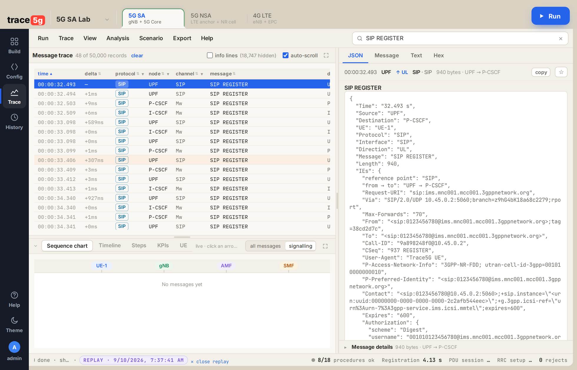
A 5G SA lab. 1 48 SIP REGISTER records, the selected one leaving the user-plane function for the P-CSCF. 2 the decode: the Request-URI and From/To in the lab's own IMS domain, the Digest challenge, and P-Access-Network-Info: 3GPP-NR-FDD, the UE telling the IMS which radio it is on.
The identities follow TS 23.003 §13: the private identity is
<IMSI>@<domain>, the public identity sip:<MSISDN>@<domain>,
and the domain is derived from the lab’s own PLMN:
ims.mnc<MNC>.mcc<MCC>.3gppnetwork.org.
Voice call: MO and MT, with real media
provenTS 24.229 §5.1.3 · TS 26.114Two registered subscribers in the same lab. One calls the other; the SDP offer and answer negotiate the media; RTP flows both ways across the radio until one of them hangs up.
// the SIP dialogue
UE-1 → INVITE sip:0123456781@ims.mnc001.mcc001.3gppnetwork.org
     ← 100 Trying · 180 Ringing
     ← 200 OK (INVITE)   // SDP answer
UE-1 → ACK
     ⇄ RTP both directions
UE-1 → BYE → 200 OK
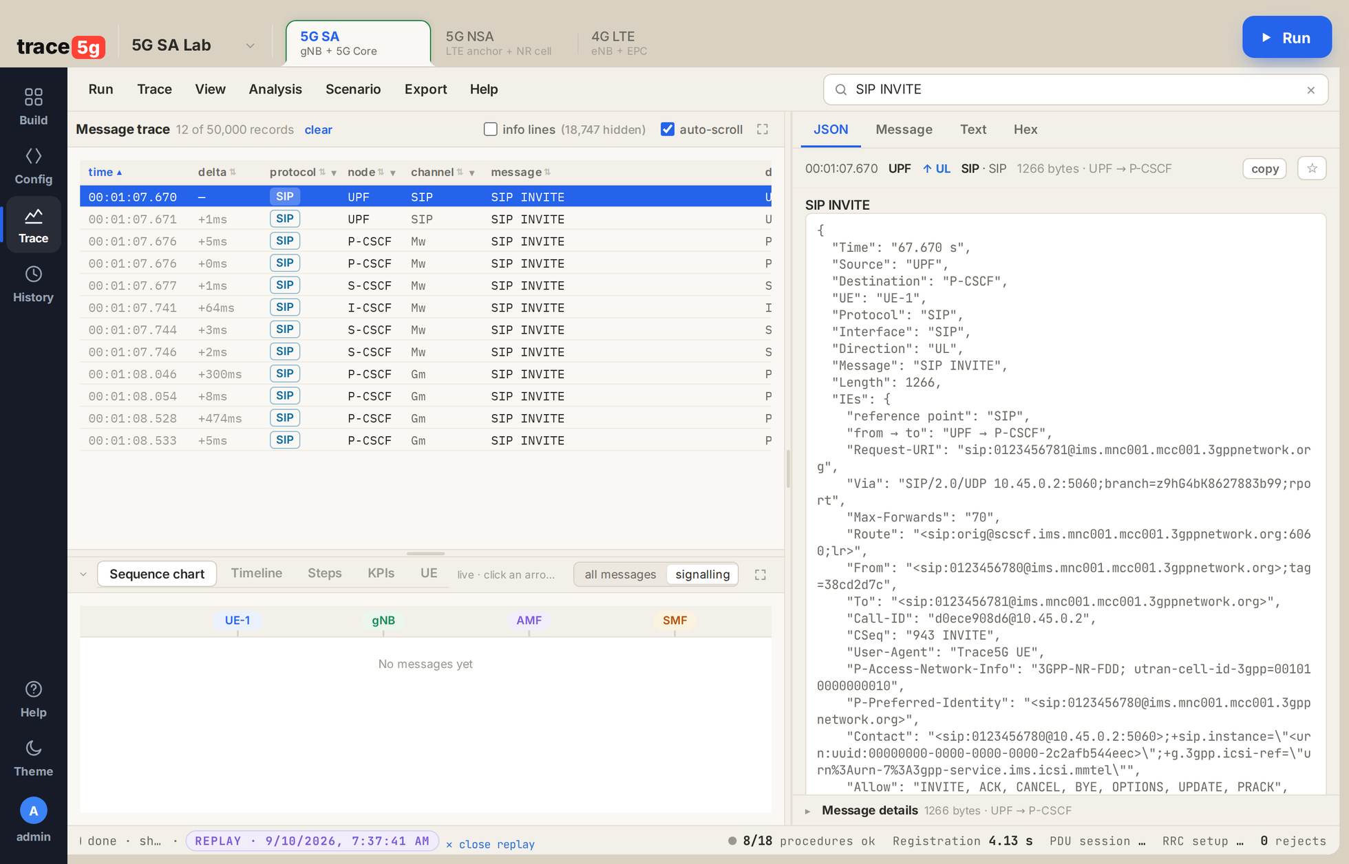
A 5G SA lab. 1 one INVITE walking the CSCF chain: to the P-CSCF, out over Mw to the I-CSCF and S-CSCF, then back down Gm to the called UE. 2 the decode: the Route to the S-CSCF, P-Preferred-Service: urn:urn-7:3gpp-service.ims.icsi.mmtel, the Accept-Contact carrying the MMTel ICSI, and the SDP offer.
The media, measured
| Lab | Leg | Seconds | Sent | Received | Bit rate |
|---|---|---|---|---|---|
| 4G-ims2 | A→B | 33.5 | 1,672 | 1,662 | 68.7 kbit/s |
| B→A | 33.4 | 1,672 | 1,669 | 68.8 kbit/s | |
| 5G-NSA-ims2 | A→B | 19.2 | 962 | 950 | 68.8 kbit/s |
| B→A | 19.1 | 956 | 956 | 68.8 kbit/s |
Packets sent and received counted per leg, so a one-way-audio fault would show as a gap between the two columns. RTP packets carried on the air: 2,726 on 4G, 1,564 on NSA.
SMS over IMS
provenTS 24.341 §5.3.2A SIP MESSAGE carrying your text from one subscriber to the other, over the same bearer the call used. You type the text in the step; it is what crosses the air.
UE-1 → MESSAGE sip:0123456781@ims.mnc001.mcc001.3gppnetwork.org
       Content-Type: text/plain
       "Trace5G lab message"
     ← 200 OK (MESSAGE)
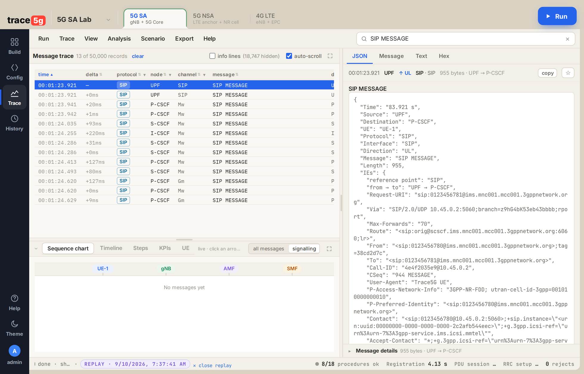
A 5G SA lab. 1 the SIP MESSAGE and its path through the CSCFs. 2 the decode: Content-Type: text/plain, Content-Length: 24, the body itself, and the raw octets under it.
saved_has_message: true).Latency: ping over the UE’s own bearer
provenICMP from the UE itself, out of its tunnel interface, through the user-plane function to the gateway. The packets cross the real air interface, so the round-trip time is the radio’s and the scheduler’s, not a loopback.
PING 10.45.0.1 (10.45.0.1) from 10.45.0.2 tun_trace5g: 56(84) bytes of data.
64 bytes from 10.45.0.1: icmp_seq=1 ttl=64 time=36.2 ms
64 bytes from 10.45.0.1: icmp_seq=2 ttl=64 time=28.4 ms
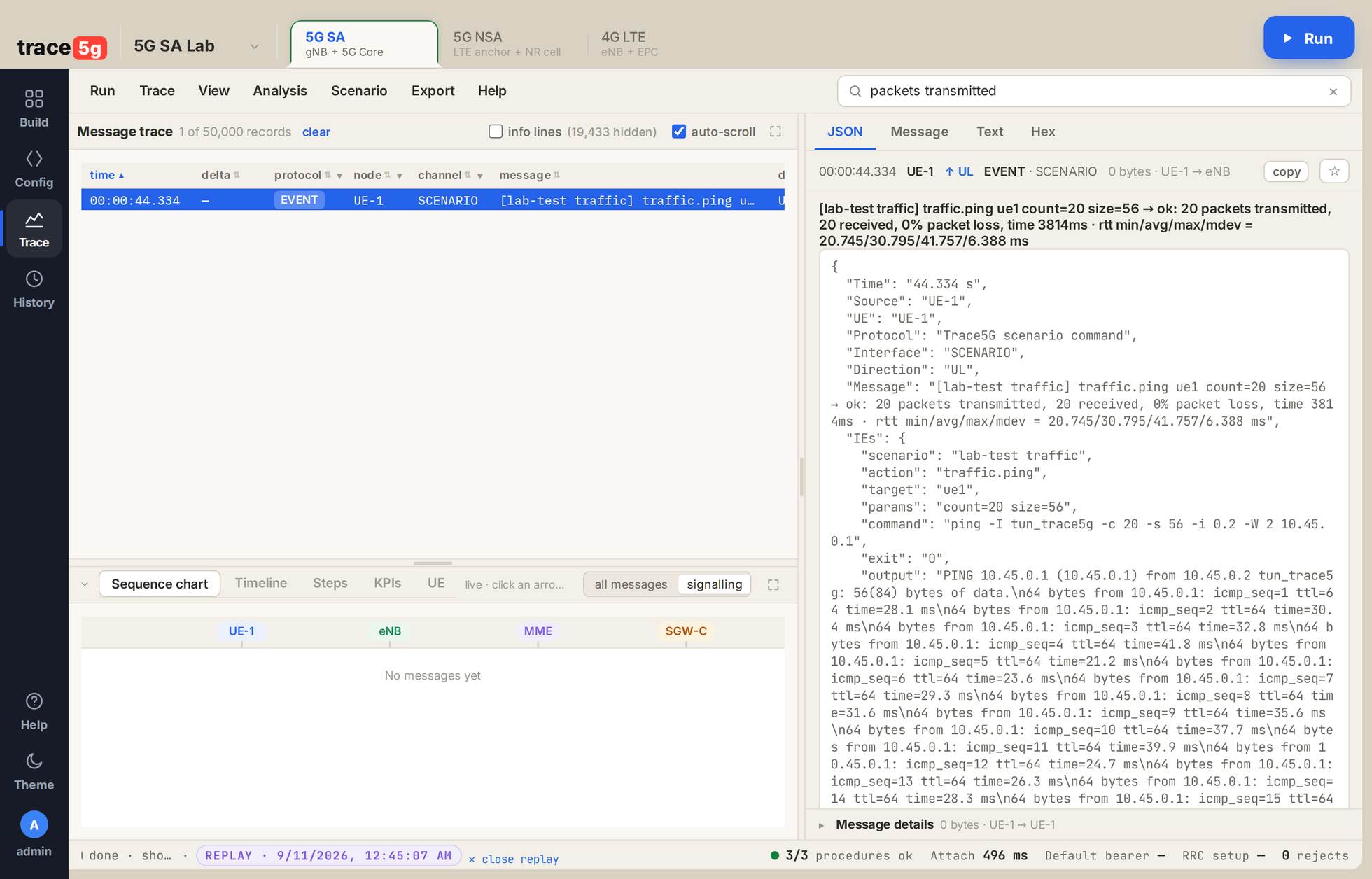
A 4G lab. 1 the scenario EVENT record for the ping step. 2 its decode: the exact command run on the UE and the complete output, 20 sent, 20 received, 0 % loss, rtt min/avg/max/mdev 20.745/30.795/41.757/6.388 ms.
RTT is the round-trip time of each packet: the fastest, the middle and the slowest of the 20 sent.
| Lab | Packet loss | RTT min ms | RTT median ms | RTT max ms |
|---|---|---|---|---|
| 4G band 3, 10 MHz | 0 % | 21 | 30 | 42 |
| 4G band 1, 5 MHz | 0 % | 24 | 30 | 44 |
| 4G band 20, 15 MHz | 0 % | 21 | 33 | 42 |
| 4G band 7, 20 MHz | 0 % | 20 | 31 | 43 |
| 5G SA, 20 MHz | 0 % | 24 | 39 | 168 |
| 5G NSA, NR n7 | 0 % | 47 | 82 | 128 |
| 5G NSA, two UEs + IMS | 10 % | 42 | 124 | 704 |
Every row is measured, including the last: a two-UE 5G NSA lab carrying an active call loses about one ping in ten, with a long tail.
Throughput: a real download
provenA timed HTTPS download over the UE’s bearer. The step runs for the number of seconds you choose, and the bytes are counted as they arrive.
downloaded 22,796,544 bytes at 2,279,654 B/s
  (connect 0.107 s, http 200) from https://speed.cloudflare.com/__down
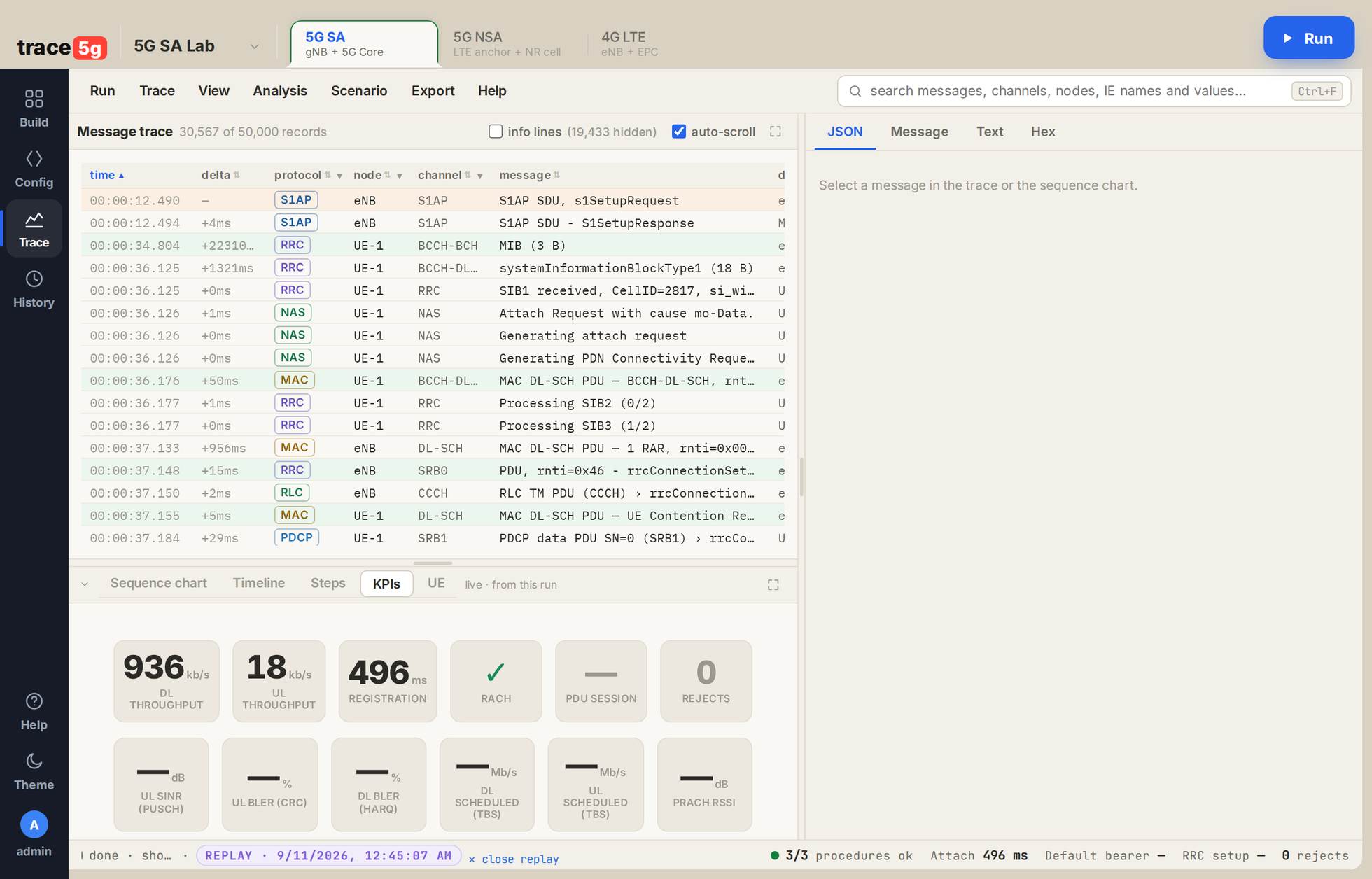
A 4G lab. 1 the KPI strip, every figure computed from this run's own records: DL 936 kb/s, UL 18 kb/s, registration 496 ms, random access succeeded, 0 rejects. The tiles reading — had no measured value in this run and are left empty rather than filled with a zero. Above the strip, the attach itself: S1 Setup, MIB, SIB1, Attach Request, random access, rrcConnectionSetup, contention resolution, InitialUEMessage.
| Lab | Bytes in 10 s | Rate | MAC DL total |
|---|---|---|---|
| 4G band 1, 5 MHz | 11,602,615 | 1.16 MB/s | 15,526,319 |
| 4G band 20, 15 MHz | 17,655,360 | 1.77 MB/s | 19,110,861 |
| 4G band 7, 20 MHz | 22,603,200 | 2.26 MB/s | 19,040,777 |
| 4G band 3, 10 MHz + 256QAM | 22,796,544 | 2.28 MB/s | 21,394,601 |
| 5G SA, 20 MHz | 7,893,824 | 0.77 MB/s | 9,705,235 |
| 5G NSA, NR n7 | 8,469,568 | 0.85 MB/s | 4,798,166 |
256QAM on the downlink
The UE declares DL category 11, which carries dl-256QAM-r12 (TS 36.306
Table 4.1A-1), and the cell answers by switching to the alternative CQI table, so the scheduler
can pick it. What the scheduler then used, over one 10 MHz download:
| DL modulation order | Transport blocks |
|---|---|
| mod={8} 256QAM | 4,004 |
| mod={4} 16QAM | 26 |
| mod={2} QPSK | 28 |
| mod={6} 64QAM | 3 |
DL MCS settled at 27 with CQI 15, and the 10 MHz cell downloaded 2.28 MB/s — what a 20 MHz cell reaches without 256QAM.
Reading a message
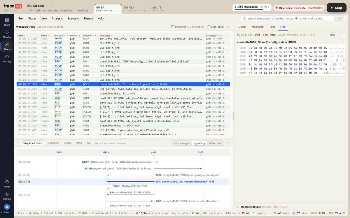
The Trace page is one screen with four parts. Everything on it is derived from the run’s own records.
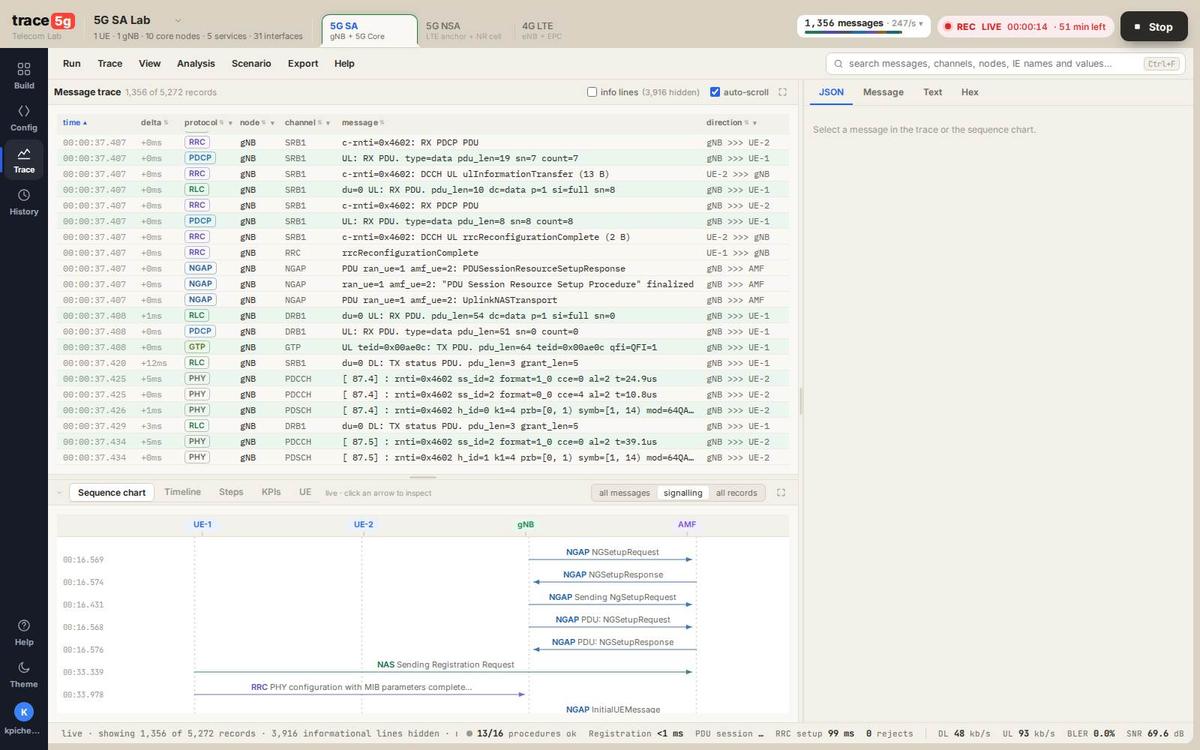
- 1Menu bar. Run, Trace, View, Analysis, Scenario, Export, Help. Filters, layouts, per-node actions and downloads all live here.
- 2Message trace. One row per record: time, delta, protocol, node, channel, message, direction. Sortable and filterable by every column. The counter above it says exactly how many of how many are on screen.
- 3Decode panes. JSON · Message · Text · Hex. Four views of the selected record, described below.
- 4Sequence chart. The same records as a ladder between nodes. Click an arrow to select that record in the table, and vice versa. Tabs beside it switch to Timeline, Steps, KPIs and UE views.
- 5KPI strip. Procedures completed, procedure timings, rejects, DL/UL rate, BLER and SNR, all computed from this run’s records.
- 6Recorder. REC state, elapsed time, time left on the run, and Stop. Clicking it while a run boots reopens the progress panel.
Screenshot: a live 5G SA run on trace5g.com, 2026‑09‑10. Status bar reads “live · showing 1,356 of 5,272 records · 3,916 informational lines hidden”.
The four panes
Select any record and the right-hand pane shows it four ways. This is one real
rrcReconfiguration, 110 bytes, sent by the gNB to UE‑2.
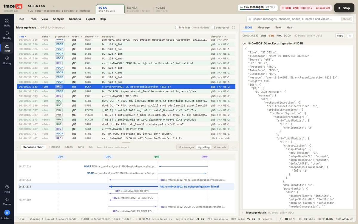
- 1The selected row in the trace, highlighted.
- 2The header of the decode: time, node, direction, protocol, channel, byte count and who sent it to whom:
110 bytes · gNB → UE-2. - 3The decode itself, here as JSON: every information element, nested exactly as the ASN.1 defines it.
- 4The same record in the ladder, selected in step with the table.
JSON: the record as data
{
  "Time": "37.333 s",
  "Timestamp": "2026-09-10T22:48:08.246Z",
  "Source": "gNB",  "UE": "UE-2",
  "Protocol": "RRC", "Interface": "DCCH", "Direction": "DL",
  "Message": "c-rnti=0x4602: DL rrcReconfiguration (110 B)",
  "Length": 110,
  "IEs": { /* the full tree, below */ }
}
Copyable from the pane. This is the shape every record has, so a trace can be processed outside the product as well as read inside it.
Message: the IE tree
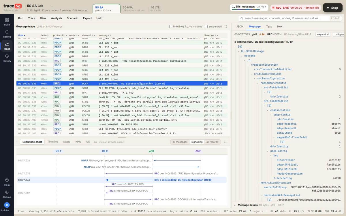
DL-DCCH-Message → message → c1 → rrcReconfiguration
  rrc-TransactionIdentifier : 3
  criticalExtensions → rrcReconfiguration
    radioBearerConfig
      srb-ToAddModList  → [0] srb-Identity : 2
      drb-ToAddModList  → [0]
        cnAssociation → sdap-Config
            pdu-Session : 1
            sdap-HeaderDL : absent
            sdap-HeaderUL : absent
            defaultDRB : true
            mappedQoS-FlowsToAdd : [0] 1
        drb-Identity : 1
        pdcp-Config → drb
            discardTimer : infinity
            pdcp-SN-SizeUL : len18bits
            pdcp-SN-SizeDL : len18bits
            headerCompression : …
What you are looking at. A data radio bearer being added, with its SDAP mapping to
PDU session 1 (TS 37.324), its DRB identity, and its PDCP configuration: 18-bit sequence numbers,
no discard timer, header compression off. Reference: TS 38.331 §6.3.2 RadioBearerConfig.
Hex: the bytes on the wire
0000  06 8a 80 40 9a 01 e0 02 05 e3 f0 a5 00 d2 c0 15   ...@............
0010  84 88 8b d7 63 80 83 2f 00 05 8e 01 86 2a fe 40   ....c../.....*.@
0020  90 69 e0 80 20 46 00 40 11 1f 80 b9 56 c3 ea 40   .i.. F.@....V..@
0030  df 80 1a 00 40 0d 4b 80 40 70 84 40 02 40 40 01   ....@.K.@p.@.@@.
0040  8c 4c
The octets the tree above was decoded from. Offset, hex, ASCII: the usual three columns, so you can check the decode against the spec yourself.
Hex per record
The hex attached to a record is capped at 256 bytes. On a 4G run of 15,626 records, 608 (3.9 %) had a PDU longer than that; the largest was a 2,112-byte MAC PDU shown with its first 256. Signalling messages are almost always well under the cap; large MAC and service-based payloads are the ones affected.Text: the flat form
00:00:37.333 [gNB] RRC / DCCH — c-rnti=0x4602: DL rrcReconfiguration (110 B)
  [0] DL-DCCH-Message
    message  c1  rrcReconfiguration
      rrc-TransactionIdentifier : 3
      criticalExtensions  rrcReconfiguration  radioBearerConfig
        srb-ToAddModList [0] srb-Identity : 2
        drb-ToAddModList [0] cnAssociation …
The same tree without punctuation, for pasting into a ticket, an email or a report.
KPIs
The strip along the bottom is computed in your browser from the records of your run. Nothing on it
is a default, and a value with nothing behind it reads — rather than zero.
| KPI | Where it comes from |
|---|---|
| n/m procedures ok | Named 3GPP procedures the trace shows completing, out of those it shows starting |
| Registration / Attach | Time from the first NAS request to the accept |
| PDU session / Default bearer | Time to establish the session end to end |
| RRC setup | rrcSetup to rrcSetupComplete |
| rejects | Rejection messages of any layer in the trace; — when there are no records at all |
| DL / UL | Bytes carried in MAC PDUs over the run, or the scheduled transport-block rate where no MAC total is available. The label says which |
| BLER | Share of HARQ transmissions the UE did not acknowledge |
| SNR | As the receiver reported it |
// read from the live page
13/16 procedures ok · Registration <1 ms · PDU session … · RRC setup 99 ms
0 rejects · DL 48 kb/s · UL 93 kb/s · BLER 0.0% · SNR 69.6 dB
A run’s full radio metrics are richer than the strip: PRB counts per direction, modulation histograms, HARQ retransmissions, PRACH count, PUCCH count, per-RNTI breakdown and timing-advance reading are all recorded.
Building a lab, running it, keeping it
Build
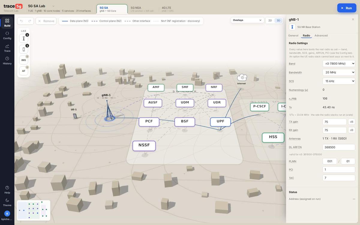
- 1Lab name and summary. UEs, base stations, core nodes, services and interfaces, counted from what is on the canvas. While a run is recording it describes the run.
- 2Technology tabs. 5G SA, 5G NSA, 4G LTE. Switching rebuilds the topology for that network.
- 3The element rail. Base stations, UEs, the voice core and the application function. Click to add; the count beside each is what the lab holds.
- 4Node inspector. Every parameter of the selected node. Here the gNB: band, bandwidth, SCS, numerology, PRB count, Ts, gains, antennas, ARFCN, PLMN, PCI, TAC.
- 5Run. Opens the run dialog.
Note Address (assigned on run) — at the bottom of the inspector: before a
run there is no address, so the field is empty rather than guessed.
Choose what happens after it boots
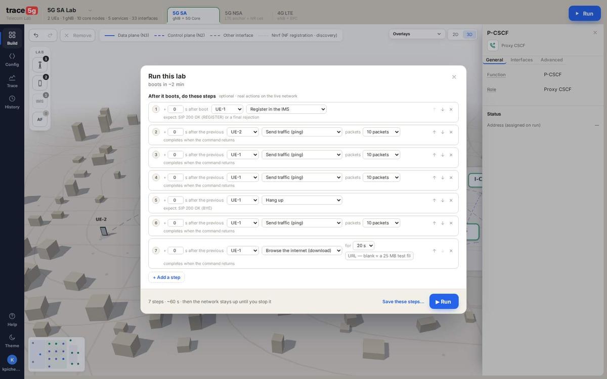
- 1Boot estimate and the promise that steps are optional: a lab can simply boot and wait for you.
- 2The steps. Each one picks a target, an action and its parameters, plus when to run it: so many seconds after boot, or after the previous step. Each row says what it expects, e.g. expect: SIP 200 OK (REGISTER).
- 3Run. The network boots and the steps execute against it in order.
What a call and a text look like as steps
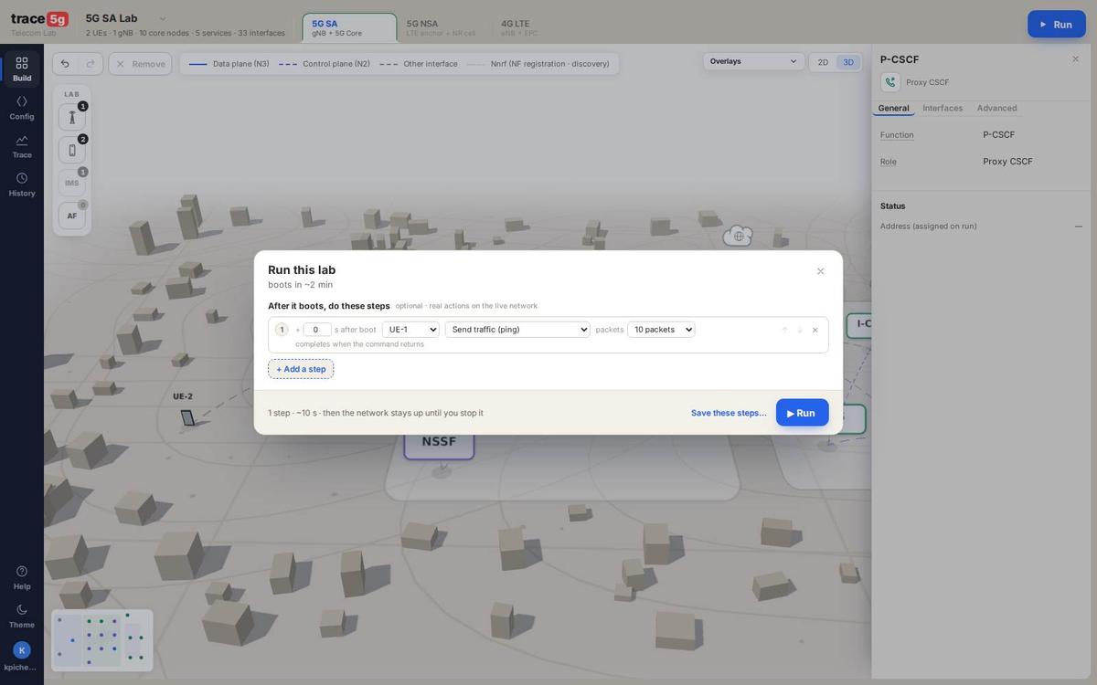
- 1With two subscribers on the voice core, the UE’s action list carries Call another UE and Send an SMS to another UE beside register, hang up, deregister and status. With only one subscriber they are absent, because a call needs somebody on the other end.
While it boots
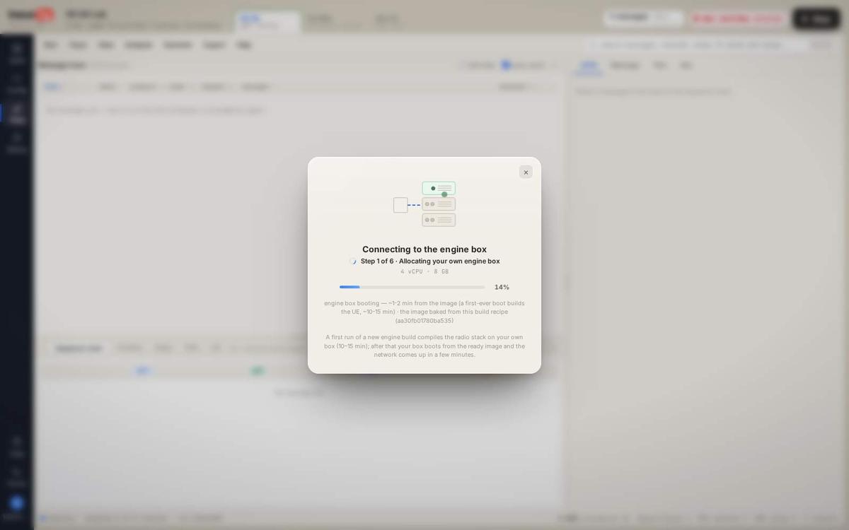
- 1The panel names the stage the run has really reached and holds there until it reaches the next one, rather than running a timer. Dismiss it and the REC chip in the header brings it back.
History and replay
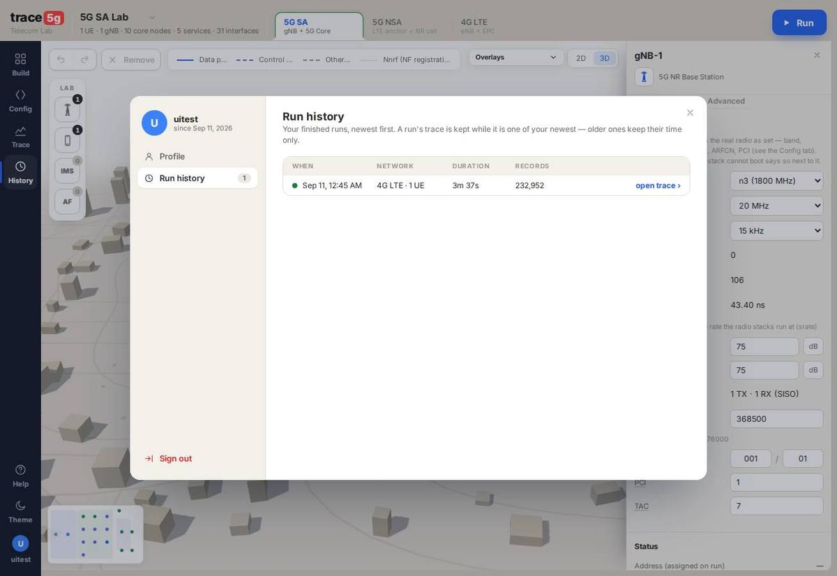
- 1Every finished run of yours: when, which network, how long, how many records.
- 2open trace reloads the whole run into the analyzer: the same table, ladder, decodes and KPIs as when it was live.
Screenshot of a saved 4G trace reopened in the analyzer (4G LTE, 1 UE, 3 m 37 s, 232,952 records).
Radio parameters are pickers, not prose
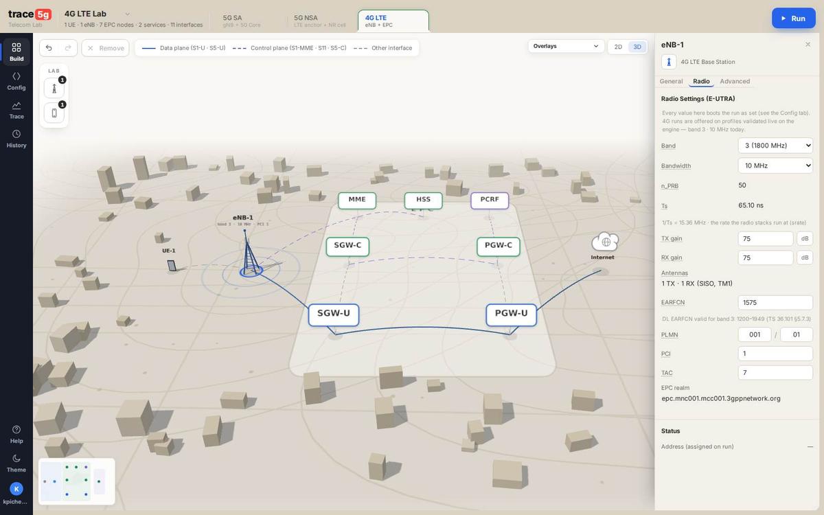
- 1Band and channel bandwidth for a 4G cell: bands 1, 3, 7, 8, 20 and 28 at 5, 10, 15 or 20 MHz. The derived facts (n_PRB, Ts, the valid EARFCN range for the chosen band) update beside them.
FAQ
What does the band setting change?
What it changes. The band goes into the cell configuration and the UE
configuration. The UE performs an actual cell search at that channel and derives the carrier from the
band’s own arithmetic: band 3, EARFCN 1575 gives f_dl=1842.5 MHz and
f_ul=1747.5 MHz, the exact 95 MHz band-3 duplex gap. The band and the downlink
bandwidth appear in the system information the UE decodes. Configure an EARFCN outside the band and
the UE finds nothing and never attaches.
Channel bandwidth does change the signal. 5, 10, 15 and 20 MHz are 25, 50, 75 and 100 PRB: a genuinely different signal, sample rate and capacity. Measured: 1.16 → 1.77 → 2.26 MB/s across 5, 15 and 20 MHz.
What is in the UE capability message?
The UE capability is decoded to the leaf, on both networks. On 5G SA it declares its band, its band combination and a feature set per direction: rel15, 15 kHz SCS, 10 MHz. On 4G it carries more: release 14, category 4, with PDCP, PHY, RF and measurement parameters, feature group indicators and inter-RAT parameters, 102 information-element nodes inside one 44-byte message.
The declared band list follows the channels the UE is configured to search, so a UE searching six channels declares six bands and can camp on any of them. The cell reads that capability and schedules to it, which is why what the UE declares is what the radio can actually do.
Can another user see my run?
No. Each run gets its own core, its own subscriber database and its own address space, and is destroyed when the run ends. History is per account.
How long does a run take to start?
Measured on trace5g.com: 1 m 40 s from pressing Run to the first decoded record.
How many UEs can one lab have?
Up to three on 5G SA and up to two on 4G and 5G NSA. Each UE runs its own real-time physical layer, which is what sets the number today.
Can I get the data out?
Yes. Every record can be copied as JSON, as an indented text tree or as a hex dump from its own pane, and the Export menu offers the run’s captures. The record shape is stable, so a trace can be processed by your own tools as easily as read in the browser.
What happens when something genuinely fails?
You see it. A refused stream, a radio link failure, a rejected registration and a step that did not complete are all reported in the words of the thing that failed, in the status bar and in the trace. Nothing is swallowed, and a field with no measured value is left empty rather than filled with a zero.
What’s new
Capabilities the platform gained, most recent first.
| When | What you can do |
|---|---|
| Sep 2026 | Six bands and four channel bandwidths on 4G and 5G NSA. Bands 1, 3, 7, 8, 20 and 28 at 5, 10, 15 or 20 MHz. The NSA secondary cell sits on n1, n3, n7 or n28. |
| Sep 2026 | 256QAM on the downlink. The UE declares DL category 11 and the cell switches to the alternative CQI table. A 10 MHz lab reaches 2.28 MB/s, what a 20 MHz lab reaches without it. |
| Sep 2026 | The 4G UE capability is decoded to the leaf. 102 information elements: release, category, PDCP, PHY, RF and measurement parameters, feature group indicators and inter-RAT parameters. |
| Sep 2026 | The UE declares every band it is configured to search, so what it advertises matches what it can really camp on. |
| Sep 2026 | Voice calls and SMS on 5G NSA. All three networks now place a call and send a text over IMS. |
Specifications
What a lab supports today. The list grows; nothing here is a permanent ceiling.
| Item | Supported |
|---|---|
| Networks | 4G LTE · 5G SA · 5G NSA (EN-DC) |
| Bands, 4G LTE | 1, 3, 7, 8, 20, 28 |
| Bands, 5G SA | n1, n3, n7, n28 |
| Bands, 5G NSA | LTE anchor on 1, 3, 7, 8, 20, 28 with an NR secondary cell on n1, n3, n7 or n28 |
| Channel bandwidth, 4G LTE | 5, 10, 15 and 20 MHz (25, 50, 75 and 100 PRB) |
| Channel bandwidth, 5G SA | n1 up to 20 MHz · n3 up to 30 · n7 up to 50 · n28 up to 40, per TS 38.101-1 (25 to 270 PRB) |
| Subcarrier spacing | 15 kHz, FDD |
| Antennas | 1 TX × 1 RX (SISO) |
| UEs per lab | up to 3 on 5G SA, up to 2 on 4G and 5G NSA |
| Downlink modulation | up to 256QAM |
| Measured throughput | 1.16 to 2.28 MB/s, with the channel bandwidth |
| Decoded layers | PHY, MAC, RLC, PDCP, RRC, NAS, NGAP, S1AP, PFCP, GTP, Diameter, SIP, SBI |
| Radio link | the cell and the UE exchange a real LTE or NR waveform: coding, modulation, HARQ, scheduling and the UE’s own cell search, sync and system-information decode |
3GPP index
The specifications this platform implements against, referenced directly in its source. Fifty-two distinct documents.
| Area | Specifications |
|---|---|
| Architecture | TS 23.002 · TS 23.003 · TS 23.214 · TS 23.228 · TS 23.401 · TS 23.501 · TS 23.502 · TS 23.503 |
| NAS | TS 24.301 (EPS) · TS 24.501 (5GS) · TS 24.229 (SIP/IMS) · TS 24.341 (SMS over IP) |
| LTE radio | TS 36.101 · TS 36.104 · TS 36.133 · TS 36.211 · TS 36.300 · TS 36.304 · TS 36.306 · TS 36.321 · TS 36.322 · TS 36.323 · TS 36.331 · TS 36.413 |
| NR radio | TS 38.101-1 · TS 38.104 · TS 38.201 · TS 38.211 · TS 38.213 · TS 38.214 · TS 38.321 · TS 38.322 · TS 38.323 · TS 38.331 · TS 38.413 |
| EN-DC | TS 37.340 |
| Core interfaces | TS 29.212 (Gx) · TS 29.228 / 29.229 (Cx) · TS 29.244 (PFCP) · TS 29.272 (S6a) · TS 29.274 (GTP-C) · TS 29.281 (GTP-U) · TS 29.500 (SBI) · TS 29.510 (NRF) · TS 29.514 (policy authorization) |
| Security | TS 33.203 (IMS) · TS 33.401 (EPS) · TS 33.501 (5G) · TS 35.205 / TS 35.206 (MILENAGE) |
| Media | TS 26.114 |